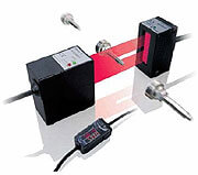
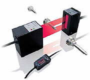
ZX-GT
Slimme lasermicrometer - Nauwkeurig en snel op alle oppervlakken
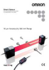
De nieuwe Smart lasermicrometer ZX-GT completeert het Omron-gamma van slimme lasermeetapparatuur. De ZX-GT kan randen detecteren, de diameter van objecten meten en nauwkeurig de positie meten op talrijke soorten materialen. De ZX-GT, die is gebaseerd op CCD-technologie, biedt hoge snelheden en nauwkeurigheid onder zware omgevingsomstandigheden. Transparante objecten, reflectieve oppervlakken of verschillende posities hebben geen invloed op het resultaat. De Smart Monitor-software voor pc kan worden gebruikt om de lasermicrometer makkelijk in te stellen en te configureren..
- Hoge graad van nauwkeurigheid: 5 - 10 µm
- Alle oppervlakken
- Grote detectieafstand: < 500 mm
- Lijnbreedte van maximaal 28 mm
- Berekeningsunit voor meerdere koppen
Specificaties & bestelinfo
Ordering information
Sensors
Controller
Accessories (order separately)
Set of interface unit and setup software PCs
Interface unit(RS-232C/binary output)
Setup software PCs
Calculating units
Receiver-controller extension cable
Specifications
Sensor
|
Visible semiconductor laser diode (wavelength 650 nm, CLASS 1 of EN60825-1/IEC60825-1, CLASS of FDA(21CFR 1040.10 and 1040.11) |
||||
|
0.5 mm dia.1 |
0.5 mm dia.1 |
|||
|
±0.1% F.S.2 |
||||
|
10 µm (number of process values to average: 16)3 |
||||
|
±0.01% F.S/C4 |
||||
|
ON: Short-circuited with 0 V or 1.5 V max. |
ON: Short-circuited with power supply voltage or |
|||
|
NPN open-collector output |
PNP open-collector output |
|||
|
1,000 lx (incandescent light)5 |
||||
|
Operating: 0 to 40°C, storage: -15 to 50°C (with no icing or condensation) |
||||
|
10 to 150 Hz single-amplitude: 0.75 mm for 80 min each in X, Y and Z directions |
||||
Controller
|
Measurement cycle6 |
1.5 ms (standard mode (NORM)) |
||
|
Analog output8 |
For current output: 4 to 20 mA/F.S., max. load resistance 300
Ω
|
||
|
Timing input, bank switching input, zero reset input, reset input |
ON: short-circuited with 0 V or 1.5 V max. |
ON: short-circuited with power supply voltage or |
|
|
NPN open-collector output |
PNP open-collector output |
||
|
Judgment output indicator: HIGH (orange), PASS (green), LOW (orange) |
|||
|
Interrupted beam width measurement, incident beam width measurement, outer diameter measurement, center position measurement, IC lead pitch, |
|||
|
Measured value, resolution, threshold, voltage output value, current output value (number of display digits can be changed) |
|||
|
Sample hold, peak hold, bottom hold, peak-to-peak hold, average hold, delay hold |
|||
|
Optical axis adjust mode/light intensityt writing mode, variable binary level, variable edge filter, analog output scaling |
|||
|
2 possible on up to two controllers (calculation Unit ZX-CAL2 is required for connecting controllers to each other.) A-B, A+B, width |
|||
|
Measurement cycle setting, threshold setting, hysteresis setting, initialization, key lock |
|||
|
Operating: 0 to 50°C, storage: -15 to 60°C (with no icing or condensation) |
|||
|
10 to 150 Hz single-amplitude: 0.35 mm for 80 min each in X, Y and Z directions |
|||
|
Case: PBT (polybutylene terephthalate), cover: Polycarbonate |
|||
Interface unit
1. Distance between emitter and receiver: 500 mm, measurement object at 250 mm from receiver. Glass ends of chamfer 0.1 mm or more can be detected in glass edge measurement mode. (at binary level 70%)
2. Linearity is given to be a typical error with respect to an ideal straight line when the distance between the emitter and receiver is 100 mm and light is blocked at a distance of 50 mm from the receiver. (On the ZX-GT2840_, the measurement object is measured at a distance of 20 mm from the receiver.)
3. The amount of fluctuation (±3 σ ) in the analog output when the distance between the emitter and receiver is 100 mm and a ZX-GTC_ is connected
4.
Change in the light cutoff value on one side when the distance between the emitter and receiver is 100 mm and the light is half-cutoff at a distance of 50 mm from the receiver (On the
ZX-GT2840_, the measurement object is measured at a distance of 20 mm from the receiver.)
6. The first response time is “measurement cycle x (number of samples to average setting + 1) + 1 ms” max. For the second response time onwards, the specified measurement cycle time is output.
7. The response time in the high-speed mode (FAST) for the IC lead pitch and IC lead width judgment modes is 1 ms.
11.
Normally, wire the sync output wire directly to the emitter's sync input wire and run the controller in the standard mode. On an NPN type controller, use an NPN type emitter, and on a PNP type controller, use a PNP type emitter. Wiring of the sync wires is not required when the controller is run in the high-speed mode.
(Note, however, that the controller becomes more susceptible to the influence of ambient light in this case.)
Hulp nodig?
Wij zijn er om u te helpen! Neem contact met ons op en onze specialisten helpen u bij het vinden van de beste oplossing voor uw bedrijf.
Neem contact met mij op ZX-GT
Dank u wel voor het insturen van uw verzoek. Wij informeren u zo snel als mogelijk.
Wij ondervinden technische problemen. Uw formulierinzending is niet gelukt. Onze verontschuldigingen hiervoor, probeer het later nog een keer. Details: [details]
Offerte voor ZX-GT
Met dit formulier kunt u een prijsaanvraag doen voor de producten van uw keuze. Vul alstublieft alle velden in die gemarkeerd zijn met *. Uw persoonlijke gegevens behandelen wij uiteraard volstrekt vertrouwelijk.

Dank u wel voor uw aanvraag. Wij zenden u de gewenste informatie zo snel als mogelijk.
Wij ondervinden technische problemen. Uw formulierinzending is niet gelukt. Onze verontschuldigingen hiervoor, probeer het later nog een keer. Details: [details]


_41(a)_instruction_sheet_en.jpg)
