G6D4
G6D4
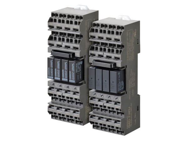
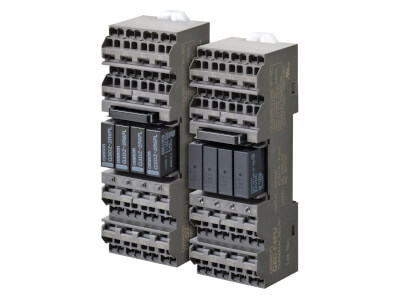
Modèle avec technologie Push-In Plus ajoutée aux relais de borne avec gamme d'unités de sortie à quatre points
- Obtention d'un rating 5 A grâce à des conceptions optimales pour une large gamme d'applications (technologie Push-In Plus).
- La borne Push-In Plus permet de diminuer les heures de travail et ne nécessite aucun resserrage.
- Les shunts (à commander séparément) facilitent le câblage commun et croisé aux bornes adjacentes.
- Méthode de double câblage permettant le câblage en dérivation (technologie Push-In Plus)
- Chaque relais possède des bobines et des contacts indépendants pour les sorties PLC compatibles (NPN et PNP).
- Les modèles de relais mécaniques et relais MOS FET de puissance (pour les valeurs nominales des contacts haute fréquence) sont disponibles.
- Un voyant de fonctionnement à LED, une diode pour l'absorption de surtension de la bobine et des outils pour pouvoir retirer facilement les relais sont inclus en standard.
- Certification UL et CSA pour les modèles standard. Certification VDE pour borne à vis, certification TÜV pour borne Push-In Plus. Classe de protection IP20 pour les modèles Push-In Plus.
Caractéristiques et références
Ordering information
Relays
| Terminal | Mounted Relay type | Contact form | Operation coil ratings | Order code
2
When your order, specify the
rated voltage. |
|---|---|---|---|---|
| Push-In Plus technology | Mechanical Relay | SPST x 4 (1NO x 4) |
12 VDC | G6D-F4PU |
| 24 VDC | ||||
| Power MOS FET relay | 12 VDC | G3DZ-F4PU | ||
| 24 VDC |
Accessories (Order Separately)
Connection socket (single sales available)
| Applicable model | Operation coil ratings | Order code
2
When your order, specify the
rated voltage. |
|---|---|---|
| G6D-F4PU/G3DZ-F4PU (Model with Push-In Plus technology) |
12 VDC | P6DF-F4PU |
| 24 VDC |
Single socket which does not mount a relay (with cover).
Short Bar (G6D-F4PU/G3DZ-F4PU (Model with Push-In Plus technology))
| Pitch | Applicable models | Number of poles | Color | Order code
2
Replace the box ( |
|---|---|---|---|---|
| 7.75 mm | G6D-F4PU G3DZ-F4PU P6DF-F4PU |
2 | Red (R) Blue (S) Yellow (Y) |
PYDN-7.75-020 |
| 3 | PYDN-7.75-030 |
|||
| 4 | PYDN-7.75-040 |
|||
| 20 | PYDN-7.75-200 |
Use the Short Bars for crossover wiring within one Socket or between Sockets.
Replacement Relay (G6D-F4PU/G3DZ-F4PU (Model with Push-In Plus technology))
| Applicable Terminal Relay Model | Operation coil ratings | Order code
2
When your order, specify the
rated voltage. |
|---|---|---|
| G6D-F4PU | 12 VDC | G6D-1A-ASI |
| 24 VDC | ||
| G3DZ-F4PU | 12 VDC | G3DZ-2R6PL |
| 24 VDC |
Parts for DIN Track Mounting
| Appearance | Type | Order code | |
|---|---|---|---|
 |
DIN Tracks | 1 m | PFP-100N |
| 0.5 m | PFP-50N | ||
 |
End Plate
2
When mounting support
rail, please use End Plate (Model PFP-M). |
PFP-M | |
| Spacer | PFP-S | ||
Specifications
G6D Mechanical Relay
Coil ratings
| Operation coil rating | Rated current (mA) |
Coil resistance (Ω) |
Must operate voltage (V) |
Must release voltage (V) |
Max. voltage (V) |
Power consumption (mW) |
|
|---|---|---|---|---|---|---|---|
| DC | 12 | 18.7 | 720 | 70% max.
2
The must operate
voltage is 75% or less of the rated voltage if the relay is mounted
in the upside down. |
10% min. | 130% | Approx. 200 |
| 24 | 10.5 | 2,880 | |||||
- Rated current and coil resistance were measured at a coil temperature of 23°C with a tolerance of ±20%.
- Performance characteristic data are measured at a coil temperature of 23°C.
- The maximum allowable voltage is the maximum value of the operating voltage for the relay coil operating power supply. There is no continuous allowance.
- The rated current includes the terminal’s LED current.
Contact ratings
| Model | G6D-F4PU (Model with Push-In Plus technology) |
|---|---|
| Load | Resistive load (cos φ = 1) |
| Rated load | 5 A at 250 VAC, 5 A at 30 VDC |
| Rated carry current | 5 A |
| Max. switching voltage | 250 VAC, 30 VDC |
| Max. switching current | 5 A |
| Max. switching capacity (reference value) |
1,250 VA, 150 W |
Characteristics
| Model | G6D-F4PU (Model with Push-In Plus technology) |
|
|---|---|---|
| Item | Relay output | |
| Contact resistance
2
Measurement
condition: 1 A at 5 VDC |
100 mΩ max. | |
| Operate time
2
Ambient temperature condition: 23°C |
10 ms max. | |
| Release time
2
Ambient temperature condition: 23°C |
10 ms max. | |
| Insulation resistance | 1,000 MΩ min. (at 500 VDC) | |
| Dielectric strength |
Between coil and contacts |
2,000 VAC, 50/60 Hz for 1 min |
| Between contacts of the same polarity |
750 VAC, 50/60 Hz for 1 min | |
| Shock resistance voltage (between coil and contacts) |
4,000 V (1.2 × 50 μs) | |
| Vibration resistance |
Destruction | 10 to 55 to 10 Hz, 0.75-mm single amplitude (1.5-mm double amplitude) |
| Malfunction | 10 to 55 to 10 Hz, 0.75-mm single amplitude (1.5-mm double amplitude) |
|
| Shock resistance |
Destruction | 500 m/s2 |
| Malfunction | 100 m/s2 | |
| Endurance | Mechanical | 20,000,000 operations min. (switching frequency: 18,000 operations/hr) |
| Electrical
2
Ambient temperature condition: 23°C |
70,000 operations min. (5 A at 250 VAC, resistive load)70,000 operations min. (5 A at 30 VDC, resistive load)(at 1,800 switching frequencies/hr) |
|
| Failure rate P Level (reference value
2 )This value is measured at 120 switching frequencies/min. |
10 mA at 5 VDC | |
| Ambient operating temperature, Ambient storage temperature |
–25 to 55°C (with no icing) | |
| Ambient operating humidity | 45% to 85% | |
| LED color | Yellow | |
| Sealing | IP20 | |
| Weight | Approx. 95 g | |
G3DZ Power MOS FET Relay Specifications
Input (per G3DZ Power MOS FET Relay)
| Rated voltage | Operating voltage | Must operate voltage level |
Must release voltage level |
Input impedance | Rated current | |
|---|---|---|---|---|---|---|
| DC | 12 | 9.6 to 14.4 VDC | 9.6 VDC max. | 1 VDC min. | 2 kΩ ±20% | 8.0 mA ±20% |
| 24 | 19.2 to 28.8 VDC | 19.2 VDC max. | 4 kΩ ±20% | 8.2 mA ±20% | ||
The rated current includes the terminal’s LED current.
Output (per G3DZ Power MOS FET Relay)
| Rated operating voltage | Load voltage range | Load current | Inrush current resistance |
|---|---|---|---|
|
5 to 240 VAC 5 to 100 VDC |
3 to 264 VAC 3 to 125 VDC |
100 μ to 0.3 A | 6 A (10 ms) |
There is no output polarity for the G3DZ.
Characteristics
| Model | G3DZ-F4PU (Model with Push-In Plus technology) |
|---|---|
| Item | Power MOS FET relay output |
| Must operate time | 10 ms max. |
| Release time | 15 ms max. |
| Output ON-resistance | 2.4 Ω max. |
| Leakage current at OFF state | 10 μA max. (at 125 VDC) |
| Insulation resistance | 100 MΩ min. (at 500 VDC) |
| Dielectric strength between I/O | 2,000 VAC, 50/60 Hz for 1 min |
| Vibration resistance | 10 to 55 to 10 Hz, 0.75-mm single amplitude (1.5-mm double amplitude) |
| Shock resistance | 500 m/s2 |
| Ambient operating temperature, Ambient storage temperature |
–25 to 55°C (with no icing) |
| Ambient operating humidity | 45% to 85% |
| LED color | Yellow |
| Sealing | IP20 |
| Weight | Approx. 95 g |
Besoin d'aide ?
Nous sommes là pour vous aider ! Contactez-nous et nos spécialistes vous aideront à trouver la meilleure solution pour votre entreprise.
Contactez-moi G6D4
Merci de votre demande. Nous reviendrons vers vous dès que possible.
Nous rencontrons des problèmes techniques. Votre demande ne peut être traitée. Veuillez nous excuser et ré-essayer plus tard. Détails :
Devis pour G6D4
Vous pouvez utiliser ce formulaire pour demander un devis sur le produit de votre choix. Merci de compléter tous les champs *. Les informations sont traitées de manière confidentielle.
Merci de votre demande. Nous vous enverrons l'information demandée au plus tôt.
Nous rencontrons des problèmes techniques. Votre demande ne peut être traitée. Veuillez nous excuser et ré-essayer plus tard. Détails :
Téléchargements